JSD2524 2.53mm M8 Lens - 102 deg FOV, 12.05mm Track
JSD2524 2.53 mm M8 Mount Lens for Compact Stereo Depth Modules
A short 1/3"-class wide-angle lens built for stereo pairs, robot wrists and embedded depth modules where housing volume is already committed.
Key takeaway: In a stereo depth camera the baseline — not the barrel — is the scarce dimension, and this lens keeps it short: a 2.53 mm design on a 1/3" imager covers 102° diagonally from a 12.05 mm optical stack inside an Ø10 mm M8 barrel. The engineering boundary sits elsewhere: a Ø7.0 mm image circle against a 1920×1200 imager whose active diagonal can run from 6.56 mm to 7.81 mm depending on pixel pitch.
1. The Engineering Problem: Everything Doubles on a Robot Wrist
Depth accuracy in a stereo camera starts with the distance between two optical axes. Move that camera onto a robot wrist and the baseline becomes the tightest dimension in the assembly: the chassis has to hold two barrels, two holders, an inertial sensor, a locked board-to-board connector and a thermal path, and still sit close enough to the end effector to reach a part held a few centimetres away.
Distance is recovered from the pixel offset between two synchronised images, so the entire front end is a pair — two barrels, two seats, two image circles on identical geometry, two focus planes that have to agree — and that pair has to fit inside the baseline the application needs. The mechanical layout therefore sets the optical budget, not the other way round.
Three failure modes recur when a stereo camera is scaled down for an articulated arm:
Two barrels, one gap. Wide rear sections collide at short baselines, and the usual fix is extra chassis height — exactly what wrist mounting was meant to avoid.
Image circle against active diagonal. A circle narrower than the sensor diagonal darkens the corners; one much wider than the diagonal spends pixels on the module wall instead of the scene.
Edge geometry that drifts between the pair. Stereo matching assumes a predictable relation between the left and right frames. Barrel distortion at the edge enlarges the rectification step, and any difference between the two units pushes residual error straight into the depth map.
The JSD2524 2.53 mm M8 imaging lens is one answer to those three constraints. This article works through its published numbers, what each number changes in a housing design, and the point where a catalogue lens becomes a calibration item.
In a stereo pair the lens is not one component. It is two components that have to behave identically, and any geometric asymmetry between them arrives as depth error.
— JSD Optics engineering note2. Read the Sensor Before the Lens
Compact stereo cameras in the wrist-mount class commonly pair a 1920×1200 global shutter colour imager with a wide-angle lens. Two numbers decide whether a candidate lens stays in the running: the active diagonal and the pixel pitch behind it.
At a nominal 3 µm pitch the active area resolves to 5.760 mm × 3.600 mm, a diagonal of about 6.79 mm — the figure that sets the image circle a stereo pair actually needs. The same arithmetic shows how little a class label carries: 1/3", 1/2.8" and 1/2.6" parts overlap across the pitch steps below.
| Assumed pixel pitch | Active area (1920×1200) | Diagonal | Image circle needed |
|---|---|---|---|
| 2.9 µm | 5.568 × 3.480 mm | 6.56 mm | ≥6.6 mm |
| 3.0 µm | 5.760 × 3.600 mm | 6.79 mm | ≥6.8 mm |
| 3.45 µm | 6.624 × 4.140 mm | 7.81 mm | ≥7.9 mm |
Run that table against the Ø7.0 mm image circle of the JSD2524 and the design boundary becomes visible: the two smaller pitches clear it with a thin margin, the largest one does not. Measure the exact part in the drawing package before the holder is released — the diagonal is what the whole optical budget is measured against.
Focal length then trades field of view against angular resolution. A camera that must see a grasp target at three centimetres and still cover its surroundings needs a short focal length, and on this sensor class 2.5 mm is roughly where that compromise lands. Distortion, focus plane and mechanical envelope follow from there, and each one has to be fixed before the housing is released.
3. What the JSD2524 Offers a Compact Stereo Pair
The JSD2524 is a 3-element M8 thread design for the 1/3" sensor class, rated for 5 MP imagers, specified at 12.05 mm total track length with a 10 mm barrel diameter. Each published figure maps onto one decision in the housing:
| Parameter | Published value | What it changes in the design |
|---|---|---|
| Effective focal length | 2.53 mm | Sets the diagonal field of view and the angular resolution per pixel |
| Field of view | 102° D / 92° H / 59° V | Covers the near working distance without tilting the module |
| Aperture | F2.4 | Light budget for indoor and machine-tending work |
| Image circle | Ø7.0 mm | Coverage for the 1/3" class, with the margin the section above quantifies |
| Distortion | <−2.57% | Stated at nominal image height, so it can be entered in a rectification model |
| Resolution rating | 5 MP | Headroom above a 2.3 MP per-eye imager |
| Mount and barrel | M8 thread, Ø10 mm | Two units sit side by side inside a narrow baseline |
| Total track length | 12.05 mm | Defines the depth from sensor plane to barrel front |
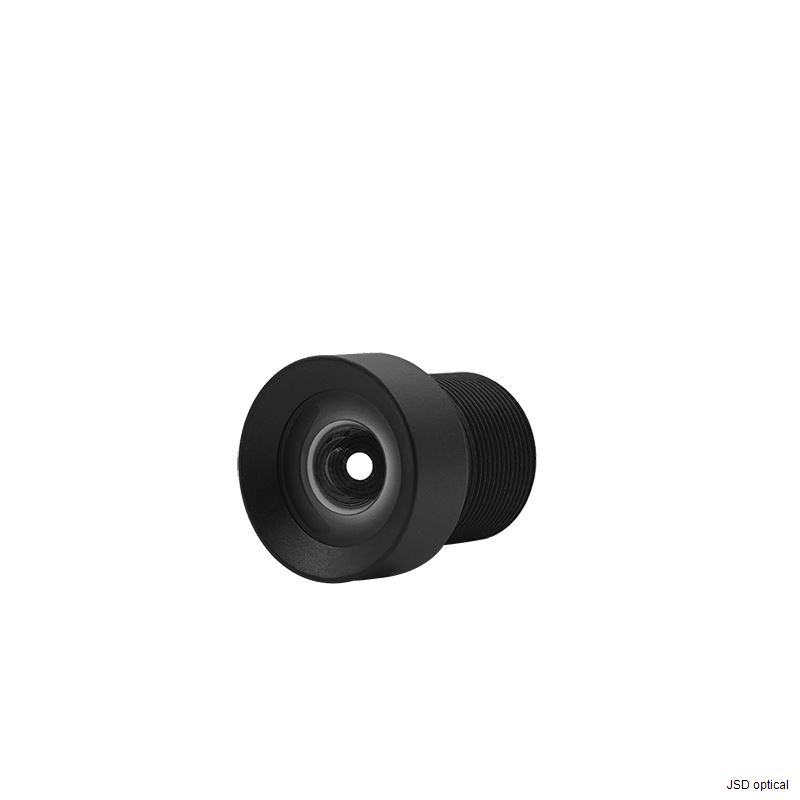
The image circle margin is the first thing to verify
A Ø7.0 mm circle against a 6.79 mm diagonal leaves about 0.2 mm, which is coverage rather than headroom. The numbers to confirm are the active diagonal of the exact part in the drawing package and the relative illumination the depth pipeline tolerates at the corners. Where a wider margin is wanted, the same design family includes 8 MP wide-angle options with larger circles and 12 mm to 16 mm barrels, which trade housing volume for corner brightness.
Distortion is a budget line, not a defect
A 92° horizontal field and a compact 3-element stack cannot both exist with no residual curvature, so the useful question is not whether distortion exists but whether the published figure is comparable. A value quoted without its image height and target geometry can sit as much as a percentage point away from the same lens measured across the full diagonal — enough to change a rectification model. The JSD2524 figure carries its image height, which gives the algorithm team a defined quantity to absorb rather than a rounded claim to re-test.

4. Where This Lens Fits
Wrist-mounted grasping and fine placement
A robot that picks a part held close to the tool needs a wide field and a short optical stack. The 102° diagonal view with a 12.05 mm track lets the module sit at the end of the arm without pushing the tool centre point forward, and the M8 thread keeps both barrels inside a baseline narrow enough for the depth range the cell requires.
Demonstration data capture for embodied AI
Imitation learning and reinforcement learning pipelines record full-resolution frames at high frame rates, so the lens should not be the bottleneck in the image chain. A 5 MP rated optic in front of a 2.3 MP per-eye imager keeps the limiting factor in the sensor and the interface rather than in the glass, and a fixed short focal length removes the repeatability question that a variable-focus module introduces.
Digital twin and simulation workflows
Sim-to-real transfer depends on a camera model that matches the physical unit: focal length, principal point and a distortion model the simulator can reproduce. A three-element design with a published distortion figure gives the simulation team a fixed target, and duplicating that geometry left and right keeps the synthetic stereo pair consistent with the captured one.
Embedded and mobile depth modules
Space-constrained platforms — handheld scanners, mobile manipulators, inspection carts — benefit from the same property: an optical stack that disappears into the envelope. The M8 thread allows shim-based focus setting at assembly, which keeps the mechanical interface simple on lower-volume builds.
5. Selecting a Wide-Angle Lens for a Stereo Pair
Selection order matters more than any single specification. Working top-down prevents a late rework of the housing:
Fix the imager and its active diagonal. Everything downstream is measured against that number.
Check image circle against diagonal at the corners. Coverage plus the relative illumination the pipeline tolerates, not coverage alone.
Choose focal length from working distance. The nearest object the application must see sets the field of view; the field of view sets the focal length.
Quantify distortion at the stated image height. The rectification model has to absorb it, and the pair has to behave the same on both sides.
Fit the mechanical envelope. Barrel diameter, thread and total track length decide whether the baseline is achievable at all.
Confirm the pair requirement. Matched focal length, principal point and distortion between the two units, plus batch consistency over the production volume.
| Decision | Generic M8 wide-angle module | JSD2524 at 2.53 mm |
|---|---|---|
| Sensor coverage | Coverage often quoted by class name only | Ø7.0 mm image circle stated against the 1/3" class |
| Edge geometry | Distortion sometimes given as a qualitative claim | <−2.57% stated at nominal image height |
| Housing volume | Longer rear sections force a taller chassis | 12.05 mm track and Ø10 mm barrel keep the module flat |
| Integration | Focus set by the holder design | M8 thread with shim-based focus at assembly |
| Engineering impact | Rectification tuned after the first samples arrive | Rectification budgeted from published figures before tooling |
The comparison is not about one part being better in the abstract; it is about how early the numbers become available. A distortion figure and an image circle that arrive before the housing is released replace a tooling iteration, and tooling iterations are what set the schedule on a compact stereo programme.
6. Engineering Considerations for Stereo Builds
Four points come up in nearly every compact stereo review. Each one is a design decision with a defined owner, not a fault in the optic.
Image circle against a larger imager
A design that moves to a larger active diagonal — a 1/2.6" or 1/2.3"-class part at 1920×1200 and coarser pixel pitch — puts the corners outside the specified circle. The fix is to step to a wider-circle member of the same wide-angle family, which costs barrel diameter and total track length and therefore baseline. Deciding that trade at the imager selection stage is far cheaper than deciding it after the holder drawing is frozen.
Focus and thread setting at assembly
M8 threads are compact and self-locking with the right adhesive pattern, but focus is a mechanical operation: the barrel rotates relative to the holder until the image plane is sharp, then it is fixed. On a stereo pair that operation has to land at the same optical position on both sides. A fixture-based focus station that checks the image on each unit is the usual approach, and the tolerance on that station becomes part of the depth error budget.
Pair matching and batch consistency
Two units leave the line with their own focal length, principal point and distortion curve. Stereo matching survives a symmetric error because rectification can absorb it; it survives an asymmetric one far less gracefully, because the residual lands directly in disparity. Production programmes therefore need defined pair-matching limits and a statement of how those limits hold across batches. These are project-specific requirements, and they are best agreed before the first volume build rather than after.
Filter and coating decisions
Infrared correction in the optical design and an infrared-cut filter in the stack are two independent decisions, and one does not imply the other. If the application needs a specific spectral response, that is a separate specification item to raise with the lens supplier while the design is still open, since it can change glass choice and therefore the distortion and focus budget.
7. Working With JSD Optics on Stereo Designs
JSD Optics designs and manufactures standard and custom imaging lenses for machine vision, robotics and embedded cameras. For stereo and multi-camera programmes the work usually starts before a part number is chosen, because the useful conversation is about the imager diagonal, the baseline and the tolerances the depth pipeline can absorb.
Optical design and in-house manufacturing. Standard wide-angle and low-distortion designs across M8, M12 and M16 platforms, plus custom development when a standard part does not fit the envelope.
Data at a stated condition. Field of view, image circle and distortion are published with their reference image height, so the algorithm team can budget rectification before tooling.
Application support at selection time. Sharing the imager part number and the working distance is usually enough to narrow the family and to identify whether the image circle margin is sufficient at the corners.
Production consistency. Pair-matching limits and batch consistency for stereo programmes are agreed as project requirements and documented for the manufacturing partner.
The practical next step is a specification exchange: send the imager part number, the active diagonal, the required working distance and the mechanical envelope, and the response can address image circle, focal length, distortion and barrel geometry in one pass. Where the numbers do not fit a standard part, the same exchange defines what a custom design has to achieve.
Most stereo optics problems are decided in the first two weeks, when the imager diagonal and the baseline are still open. After that the housing fixes the answer.
— JSD Optics application engineering8. Frequently Asked Questions
How do I choose a lens for a compact stereo depth camera?
Start from the imager: measure the active diagonal, then check the image circle against it with margin for relative illumination at the corners. Choose the focal length from the nearest working distance the application must see. Confirm the distortion figure is stated at a defined image height, then fit barrel diameter, thread and total track length to the baseline the module needs. Finally, define how closely the two units must match in focal length, principal point and distortion.
What sensor class does the JSD2524 cover?
The JSD2524 is specified for the 1/3" class with a Ø7.0 mm image circle, which covers a 1920×1200 imager at a 3 µm pixel pitch with roughly 0.2 mm of margin. A larger active diagonal, such as a 1/2.6" or 1/2.3"-class part of the same resolution, needs a wider image circle and therefore a different member of the wide-angle family.
What do the distortion and field of view figures of the JSD2524 mean in practice?
The published figures are 102° diagonal, 92° horizontal and 59° vertical with distortion below −2.57% barrel at nominal image height. A 92° horizontal field lets the module see a grasp target held close to the tool without tilting, while the barrel distortion is a quantity the rectification stage absorbs rather than a defect to remove optically.
Can two JSD2524 units be matched as a stereo pair?
That is a project specification rather than a catalogue property. Two units have to agree in focal length, principal point and distortion curve closely enough that residual error after rectification stays inside the depth budget, and those limits should be agreed before volume production so they can be held across batches and documented for the manufacturing partner.
Does the M8 barrel limit the achievable stereo baseline?
It works in the opposite direction. An Ø10 mm barrel with a 12.05 mm total track length occupies less width and depth than a comparable M12 design, which leaves room for two barrels, a holder wall and a connector inside a short baseline. The constraint to check is front clearance and the seat depth behind the thread, not the barrel width.
Is an infrared-cut filter included with the JSD2524?
Infrared correction in the optical design and an infrared-cut filter are independent decisions, and one does not imply the other. Any spectral requirement should be raised as a separate specification item while the design is still open, because filter and coating choices can change the optical stack and therefore the distortion and focus budget.
Have a stereo camera envelope to fill?
Send the imager part number, the active diagonal, the working distance and the barrel space available — the reply covers image circle, focal length, distortion and mechanical fit.
Or email us at sales@jsdoptical.com
JSD2524 · 2.53 mm M8 mount wide-angle lens · 1/3" class · M8 thread, Ø10 mm barrel, 12.05 mm total track length
 Consult now