M12 Lens for OmniVision OS02H10 CCTV: EFL, F/#, Distortion
M12 Lens Selection for the OmniVision OS02H10: Focal Length, Distortion and Night-Vision Trade-offs
A 1/2.8-inch, 1080p sensor with a 6.42 mm image diagonal sets the first filter, then field of view and distortion decide the rest.
Key takeaway: The OS02H10 is a 1/2.8-inch, 1920 × 1080 sensor with 2.9 µm pixels and a 6.42 mm image diagonal, so a paired lens has to project an image circle wider than roughly 6.6 mm once holder tolerance is counted. JSD3422 at 3.45 mm and JSD3220 at 3.19 mm both clear that floor; the choice between them is a scene decision, and the rest of a typical lens inquiry is answered from measured data for the specific part rather than from a format label.
Start with the sensor, not the lens
Most CCTV lens projects open with a focal length carried over from an earlier product, and the parameter list in the inquiry — format, focal length, aperture, infrared behaviour, drawings, operating temperature — gets treated as a dozen independent questions. They are not independent. Fixing the sensor numbers first turns the list into a sequence, because the sensor decides what has to be covered before any focal length is worth discussing.
The OS02H10 is a 1/2.8-inch format CMOS sensor with 1920 × 1080 effective pixels at a 2.9 µm pixel pitch. Its photosensitive area measures 5587.34 µm × 3153.02 µm, which puts the image diagonal at about 6.42 mm. That measurement, not the "1/2.8-inch" label, is the entry condition for lens selection.
The pixel pitch sets a second condition. At 2.9 µm the sampling limit sits near 172 line pairs per millimetre, so a 2MP-rated lens runs at the edge of what the sensor resolves, while a 5MP-rated design keeps room for interpolation, electronic zoom and digital cropping in the ISP. The brief is easier to defend when it reads "5MP class against a 2MP sensor" instead of "2MP, the frame is only 1080p".
The split that follows organises the rest of this page. The sensor datasheet settles the format, the diagonal and the sampling limit; aperture, resolution class, distortion, infrared focus shift, relative illumination and the mechanical envelope are properties of the lens. Those five items can only come from measured data or a drawing for the specific part, and a catalogue column is not a substitute for either.
"The image circle either covers the 6.42 mm diagonal or it does not. Focal length, aperture and optical coatings can be traded against one another; coverage is a pass or fail test."
— Selection rule applied to every part on this pageImage circle: the filter that ends most debates
An imaging lens projects a circular field, and the sensor rectangle has to sit inside it. When the rectangle is wider than the circle, the corners receive no light and the vignette stays in the image. The geometric requirement here is 6.42 mm; allowing for assembly decentring, holder tolerance and module tilt, the practical floor is about 6.6 mm.
Catalogue columns keep this ambiguous. Lenses sold as "1/2.8-inch" publish image circles from 6.4 mm to 8.0 mm, because vendors use the format label as a class name rather than a measurement. A part tagged for a slightly smaller format can still cover the sensor, and a part tagged for the same format can miss it by a fraction of a millimetre. The label works as a first filter; the effective image circle has to be confirmed for the exact part before a housing drawing is released.
Confirm with a measurement, not a label — request the effective image circle and the relative illumination curve for the specific part, then check corner brightness on a bench image at the F-number the build will ship with.
Oversizing is not free — a 1/1.8-inch part covers the frame, but the extra glass shows up in barrel diameter and module depth, which is where slim housings fail first.
Tolerance belongs in the drawing — the 0.2 mm reserve has to sit in the enclosure drawing and the holder stack, not only on the lens datasheet.
Focal length and field of view
Once coverage is settled, focal length becomes a scene question: at what distance the camera has to recognise a face, read a plate, or simply hold a doorway. Short focal lengths widen the view and stretch the corners; long focal lengths compress the view and drop context. Most fixed 1/2.8-inch CCTV products sit in the 3 mm to 3.5 mm band, which covers a 3 m to 8 m subject zone in a 1080p frame without pushing distortion to the point where the ISP has to rebuild geometry.
The standard M12 parts for a 1/2.8-inch, 1080p security sensor, with the figures published for each model:
| Model | EFL | F/# | FOV (D/H/V) | Distortion (measured) | Resolution | TTL |
|---|---|---|---|---|---|---|
| JSD2019 | 2.11 mm | F2.4 | 128° / 110° / 70° | <8.4% | 8MP | 16.70 mm |
| JSD3021 | 2.90 mm | F2.0 | 123° / 104° / 56° | <−19.36% | 5MP | 15.21 mm |
| JSD3220 | 3.19 mm | F2.0 | 127° / 106° / 57° | <−15.6% | 5MP | 16.76 mm |
| JSD3422 | 3.45 mm | F2.2 | 84° / 75° / 47° | <−0.73% | 5MP | 14.51 mm |
| JSD5019 | 5.00 mm | F2.4 | 65° / 58° / 34° | <−0.94% | 2MP | 14.00 mm |
| JSD5038 | 6.00 mm | F2.4 | 56° / 50° / 29° | <−0.5% | 2MP | 14.00 mm |
The table reads as three bands rather than a ranking. The 2.11 mm and 2.90 mm parts buy corridor width and accept barrel distortion above 15 percent. The 3.19 mm and 3.45 mm parts sit where most fixed CCTV products sit, holding a doorway or a short approach. The 5.00 mm and 6.00 mm parts keep distortion under one percent and suit gates and plate work, though both are 2MP designs, so headroom against a 2.9 µm pixel is thinner.
Distortion: read the measured number
Distortion gets quoted loosely in catalogues and checked late in validation. A wide lens that bends a doorframe by 15 percent still produces a usable picture, but anything downstream that assumes straight lines — people counting, plate reading, measurement, AR overlays — inherits the bend and pays for it in rectification load and lost pixels.
What makes the figure usable is the test condition behind it. Measured distortion in this class is normally reported for full field, and the negative sign marks the barrel direction; the number describes how far a straight line departs from straight at the frame edge, which is why parts are only comparable at the same field height. A sub-one-percent figure states that residual barrel stays small enough for most CCTV software to ignore. A 120° design quoting 15 percent states the opposite: the rectification stage belongs in the architecture from the first prototype, not in a field trial.
Relative illumination belongs beside distortion, because the two fail in the same corner of the frame. Neither is a standard catalogue column, so both are best requested as curves — distortion against field height, illumination against field height — and reviewed at the F-number the production build will use, since stopping down changes both.
Two sensible starting points
For a 1/2.8-inch 1080p CCTV product the shortlist narrows to two parts that clear the 6.6 mm circle with margin and sit in the useful focal band. Which one wins is a scene decision, and the two differ in more than optics.

JSD3422 — the low-distortion compact
A 1G4P design with a Ø6.6 mm image circle and a 5MP rating. Its measured distortion keeps straight edges close to straight, which removes rectification work from the ISP and keeps the frame usable for recognition and scanning; the short track length sets how shallow the housing can be. The trade is a narrower view and a slower aperture, so it fits a defined subject zone rather than area coverage.
JSD3220 — the wide, sealed option
A 5G1MG design with a 5MP rating in a sealed, ingress-rated barrel. The F2.0 aperture gathers more light at a given exposure time, which night colour and low-light scenes consume, and the metal-and-glass body suits outdoor pole and wall mounting. The wide view arrives with published barrel distortion above 15 percent, so a build that measures geometry should plan the rectification stage with the ISP team from the first prototype.
| Decision driver | JSD3422 | JSD3220 |
|---|---|---|
| Scene the lens serves | Doorway, porch, close-range recognition | Yard, corridor, wide-area coverage |
| Straight-line geometry | Measured distortion under one percent | Rectification stage planned with the ISP |
| Light budget after dark | F2.2 aperture | F2.0 aperture |
| Housing depth | Short barrel, slim dome or doorbell bezel | Deeper body, conventional turret |
| Outdoor exposure | Sealing to be specified per build | Sealed barrel, ingress rated |
Night vision: two separate decisions
Night operation is where procurement documents merge two decisions into one, and the cost surfaces at the first night field test. A working day/night camera needs both, specified apart.
The first is the IR-cut filter mechanism in the camera body. A mechanical switcher removes the filter after dark so the sensor receives 850 nm or 940 nm illumination, and replaces it in daylight so colour stays correct. It is a body-level part that has to fit around the barrel, so its clearance belongs in the enclosure drawing. Removing the filter glass also changes the optical path, which is why switcher travel and lens focus reference are designed together rather than in sequence.
The second is the optical design of the lens itself. Glass refracts differently at 850 nm than at 550 nm, so a lens corrected only for visible light moves its focus point under infrared illumination and the night image loses sharpness. An IR-corrected design holds that shift small across the working band. The two effects stack: where the filter change is not accounted for and the lens is not corrected for infrared, the module carries two focus errors at once, and daylight testing shows neither of them.
850 nm — stronger sensor response and some visible red glow at the illuminator; the usual choice for discreet indoor work.
940 nm — no visible glow and weaker response, so more illumination or a wider aperture is needed to keep exposure time practical.
What to request — measured focus shift at the wavelength in use, relative illumination across the field, and the switcher interface drawing.
The OS02H10 uses Nyxel near-infrared sensor technology, and the sensor vendor cites response at both 850 nm and 940 nm. That is a property of the sensor and says nothing about the lens, so a night-vision claim in a product specification should rest on measured lens data at the wavelength in use, or be written as pending that data.
Mechanical envelope and sealing
Optical numbers decide whether an image is possible; mechanical numbers decide whether the product can be built. Three dimensions carry most of that weight: total track length, barrel diameter, and the thread that joins lens to holder.
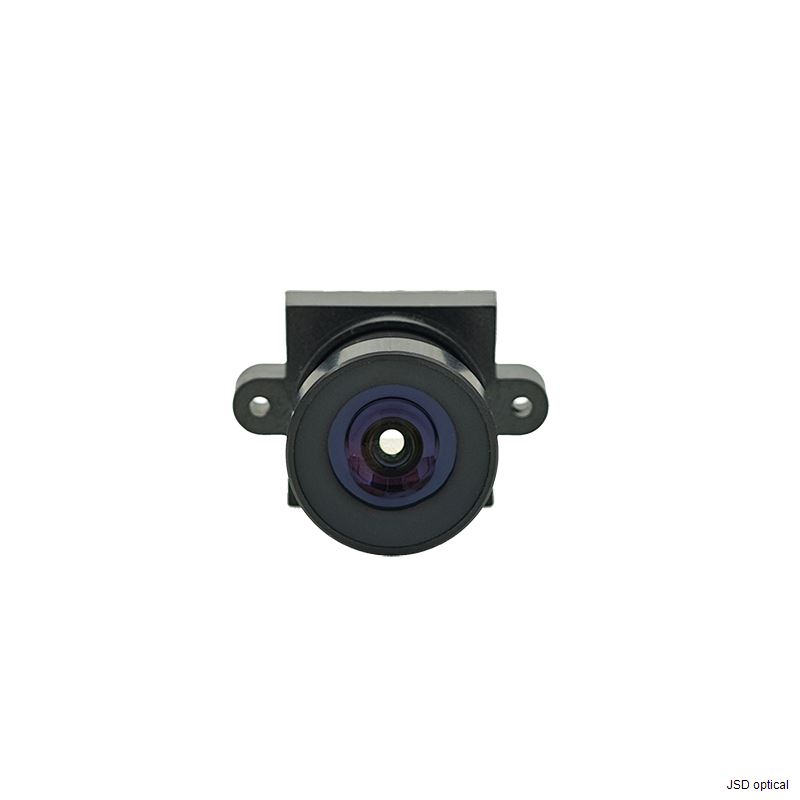
M12 × P0.5 is the de facto standard for compact CCTV modules, which keeps holder sourcing simple and lets one housing accept several focal lengths from the same family. Track length is the dimension that constrains the enclosure, and the TTL column in the focal ladder above spans 14.00 mm to 16.76 mm — a housing drawn around the longest part will not close on the shortest without a different holder stack.
Sealing needs the same care. Some parts in this family carry a sealed, ingress-rated barrel for exposed mounting; others ship unsealed and rely on the enclosure. Neither is a fault, but the specification should state which one the build assumes, because an unsealed barrel inside a gasketed dome and an unsealed barrel on an exposed pole become different products with different service lives.
Temperature is the last field usually inferred rather than specified. The OS02H10 is rated from −30 °C to +85 °C, and the lens has to hold focus and keep its cement intact across the range the module will actually see. Ask for the lens operating range in writing and read it together with the enclosure sealing detail, since a gasket or a potting compound can move the module limit before the glass does.
How to run the evaluation
A camera project moves faster when the validation order matches the cost of changing a decision. Coverage and mechanics are expensive to change once tooling exists; firmware tuning is cheap.
Confirm the image circle in writing — request the effective image circle for the specific part, and carry the 0.2 mm reserve in the drawing rather than in a conversation.
Frame the scene before choosing a focal length — install distance and the smallest detail that must be resolved decide whether the answer is 3.19 mm, 3.45 mm or 6.00 mm.
Test distortion on a straight-line target — photograph a grid or a doorway at the real installation distance, then compare the measured curve with what appears on screen.
Evaluate at night, not in the lab — run the module with the intended 850 nm or 940 nm illuminator, then check corner sharpness and focus shift against the visible-light reference.
Freeze the mechanical stack — lock TTL, holder height and switcher clearance before the enclosure drawing is released.
Steps one, two and four are the ones that need measured data rather than a catalogue, and the package that shortens the loop is small: effective image circle, distortion and relative illumination curves, a 2D drawing of the specific part, and the operating temperature range for the build under review. A supplier who returns that package is answering the inquiry; a part number alone is not an answer.
❓ Frequently Asked Questions
Which M12 lens fits the OmniVision OS02H10?
Any part whose effective image circle exceeds the 6.42 mm diagonal covers the frame, and about 6.6 mm is the safe floor once holder tolerance is counted. JSD3422 at 3.45 mm and JSD3220 at 3.19 mm are the two parts on this shortlist, both 5MP-rated against a 2.9 µm pixel pitch.
What focal length gives the right field of view for CCTV work?
Work back from the scene instead of forward from a preference. The scene width the camera must cover, divided by the sensor width, gives the magnification the install distance has to deliver, and focal length follows from that number. On a 1/2.8-inch sensor a 3.45 mm part frames a doorway across a 3 m to 8 m approach, a 2.11 mm part holds a corridor, and a 6.00 mm part reads a plate at a gate.
Can these lenses be used for night vision?
Two conditions apply and neither implies the other: an IR-corrected optical design that holds focus under infrared illumination, and a mechanical IR-cut switcher in the camera body. An IR-corrected lens does not include a filter switcher, so measured focus shift and relative illumination at the wavelength in use should be requested for the specific part before a night-vision claim is written.
How much distortion is acceptable?
It depends on what the image feeds. Recognition, scanning and geometry measurement sit comfortably below about one percent; wide 120° views commonly publish 15 percent or more and need the rectification stage planned with the ISP team from the first prototype, because rectification costs both processing time and usable pixels.
What mechanical details are needed before tooling a housing?
Four numbers settle the mechanical stack: total track length, barrel diameter, the M12 × P0.5 thread, and the clearance the IR-cut switcher needs. Ask for the drawing of the specific part rather than of the family, because the parts in this group differ in track length and a housing drawn around one will not close on another.
Match a lens to your OS02H10 module
Share the sensor, install distance and scene; the reply carries measured distortion, image circle, a 2D drawing and the temperature range.
Or email us at info@jsdoptical.com
 Consult now